When Bill McKirgan told me he had an old Bassman 50 that "sort of" worked, I thought it would be an interesting challenge. A couple months earlier, I'd bought a 1974 Bassman 100 to go with Bill's old Ampeg V-6B cab and had to learn the basics of updating an old tube amp. A lot of what I learned came from the Hoffman Amps, where a detailed step-by-step process is described for working on old Fender amps.
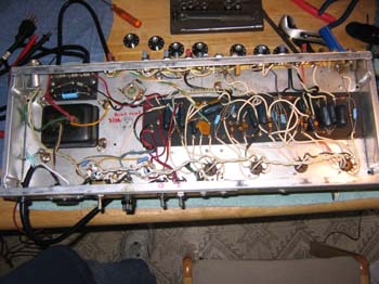
Here
is an overview of the amp chassis after I was all done. I didn't take
a "before" photo, but imagine that every part that is light blue used
to be white or brown parts.
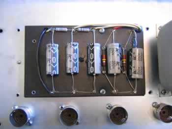
The circles at the bottom are the preamp tube sockets.
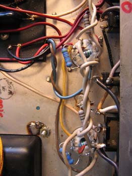
Bill
told me that one of the 6L6GC power tubes fell out when he located
the amp in his garage. I decided to replace the two old tube sockets
to
make sure that didn't happen again. These are the white circles on the
right. The old ones were brown plastic, while these are ceramic instead.
The blue resistors across the sockets and to the left are new resistors.
I wish I know electronic theory and correct names. On the top socket,
the left resistor was cracked in half and the tube didn't light. Essentially,
the amp was running on one power tube.
The gray resistors with the brown and black stripes about each socket
were installed to measure and adjust idle bias on the power tubes.
The switch to the right of the lower tube socket used to have a capacitor
to shuttle either of the power wires to ground to help reduce hum. This
is now known as the "death cap" because it sends current to a guitar
if it fails.
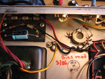
In
the original amp design, Fender "improved" the bias system for the
power tubes by changing from an actual bias adjustment to a bias balance.
Because
tubes are generally now sold in matched pairs or quads, the balance
adjust is of little use and requires hardwiring resistors to change
the bias.
The pot on the upper right is the bias balance pot rewired to become
a bias adjust pot. This mod removed a capacitor and changed a couple
of resistors on the main board.
The blue capacitor on the upper left replaced an old white one by Mallory.
In general, electrolytic caps have a life of about 10 years before they
stop doing their job.
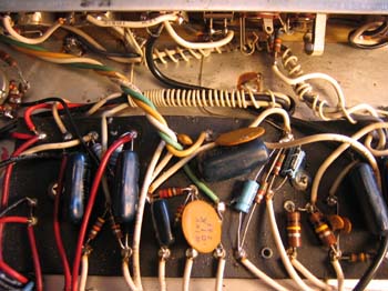
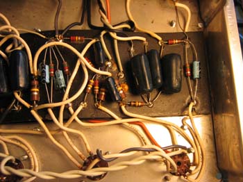
This
is another section of the main circuit board, with three more light
blue replacement capacitors. The one on the far right was originally
an odd
value and was replaced with a more common capacitor.
Note the preamp tube sockets near the bottom. Another photo shows how
the again "improved" hum balance circuit was removed and replaced with
a static circuit. The new circuit cut hum quite a bit.
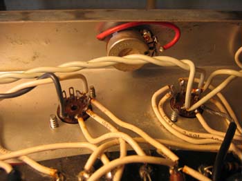
The two wires were removed and the circuit relocated to the rear of the pilot lamp. Now the pot is just a "hole filler."
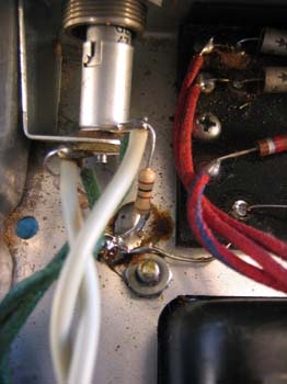
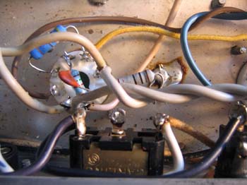
You can also see the gray bias checking resistor and the ground switch with the removed death cap. The yellow wire connects the two power tubes and was originally white. The original was too short to reuse with the new sockets. Most wires in this amp are stranded with plastic insulation. The yellow one is cloth insulated with a solid wire (thanks to Jim Rossen for the piece of wire, many components, and a foot of emergency solder).
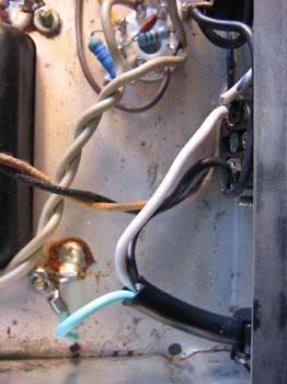
Here is the replacement power cord, with green, black and white wires. I needed to get some lugs to solder to the wires and the attach to the back of the accessory outlet and a chassis ground.
In the bottom right is the power cord strain relief that keeps the cord from being pulled out of the chassis. It also protects the wire from being cut by the edges of the metal hole it goes through. The write-ups I found online about replacing the strain relief were mysteries and talked about squishing cables with a vise or buying a specialized tool that's hard to find.
The strain relief replacement turned out to be easy. Jim Rossen suggested cutting the old cord on both sides and pulling out the inner wires individually. That worked great. The tab on the strain relief then was pressed into place with channel lock pliers and pushed through the chassis hole.
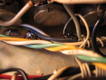
Some solder was flowed across the cracks in hope that they will be more stable. Eventually, a hotter iron will need to do the job correctly. The new solder shows as the slightly shinier areas near the center line of the photo, above the twisted green-yellow-white wires.
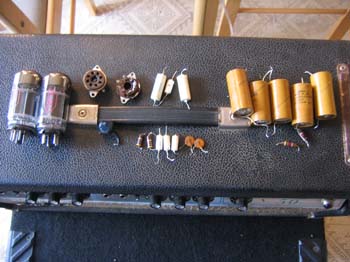
Here
is the amp all buttoned up and ready to use. The parts on the top were
removed during renovations. On the left are the old power tube, one
of them actually powerless. They had these odd wafer bases that actually
were pushed out by the spring retaining clips.
Next are the crusty old tube sockets, then the old white electrolytic
capacitors (along with a couple of resistors and disk capacitors.
Finally, the yellow tubes with the wires that look like firecrackers
are the big filter capacitors from the power supply side of the chassis.
At moderator volumes, this amp has a nice smooth deep sound, unlike the
more precise sound of modern solid state amps. Fun!